Chassis Setup
How to configure the mikLib chassis in robot-config.cpp
Please follow this setup thoroughly as almost all mistakes occur here.
Drivetrain
The first step is to configure your drivetrain motors, each motor takes in 4 values, the port, reversed, cartridge, and name.
| Cartridge | RPM | Name |
|---|---|---|
| Red | 100 | red_36_1 |
| Green | 200 | green_18_1 |
| Blue | 600 | blue_6_1 |
// Motor on port 1 with a blue cartridge that is not reversed
mik::motor(PORT1, false, blue_6_1, "my motor")
Right and left are from facing behind the front of the robot, or the robots point of view.
If you are using 5.5W motors in the drivetrain, use a cartridge of
green_18_1.
To determine the port of your motor you can open the device menu on the brain and unplug the motor and see which port disappears. Do this for the left and right side of the drivetrain.
// Left drivetrain motors (left/right is looking from behind the robot)
mik::motor_group({
    mik::motor(PORT1, false, blue_6_1, "left front motor"),
    mik::motor(PORT2, false, blue_6_1, "left middle motor"),
    mik::motor(PORT3, false, blue_6_1, "left back motor")
}),
// Right drivetrain motors
mik::motor_group({
    mik::motor(PORT4, false, blue_6_1, "right front motor"),
    mik::motor(PORT5, false, blue_6_1, "right middle motor"),
    mik::motor(PORT6, false, blue_6_1, "right back motor")
}),
When applying a positive voltage, all the drivetrain motors need to spin forward. To find which motors are reversed you can run the program, press the Config tab at the top left, then press Motor Menu at the bottom left. You should then see a screen with all the motors ports laid out. Press the right arrow next to the motor to spin it forward. Press the arrow again to stop the motor. If the motor does not spin forward then set the value to true.
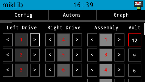
I am attempting to spin the left motor on PORT1 forward at 12 volts. Since the text is red that means its not plugged in.
Holonomic
If you are using a X-Drive or Mecanum drivetrain all the same steps apply but you need to include whether they are front or back motors
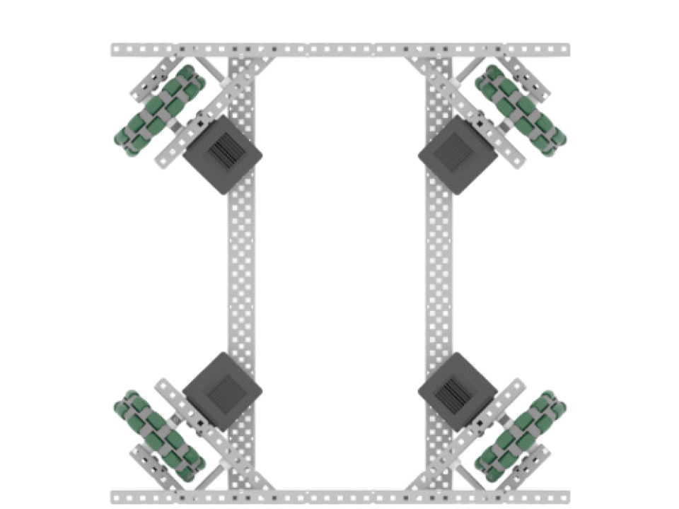
// Left drivetrain motors
mik::motor_group({
    mik::motor(PORT1, false, blue_6_1, "left front"),
    mik::motor(PORT3, false, blue_6_1, "left back")
}),
// Right drivetrain motors
mik::motor_group({
    mik::motor(PORT4, false, blue_6_1, "right front"),
    mik::motor(PORT6, false, blue_6_1, "right back")
}),
Inertial Sensor
mikLib requires an inertial sensor. Make sure your inertial sensor is lying down flat. To reduce vibrations that cause the sensor to drift it is recommended to mount it on foam or rubber links.
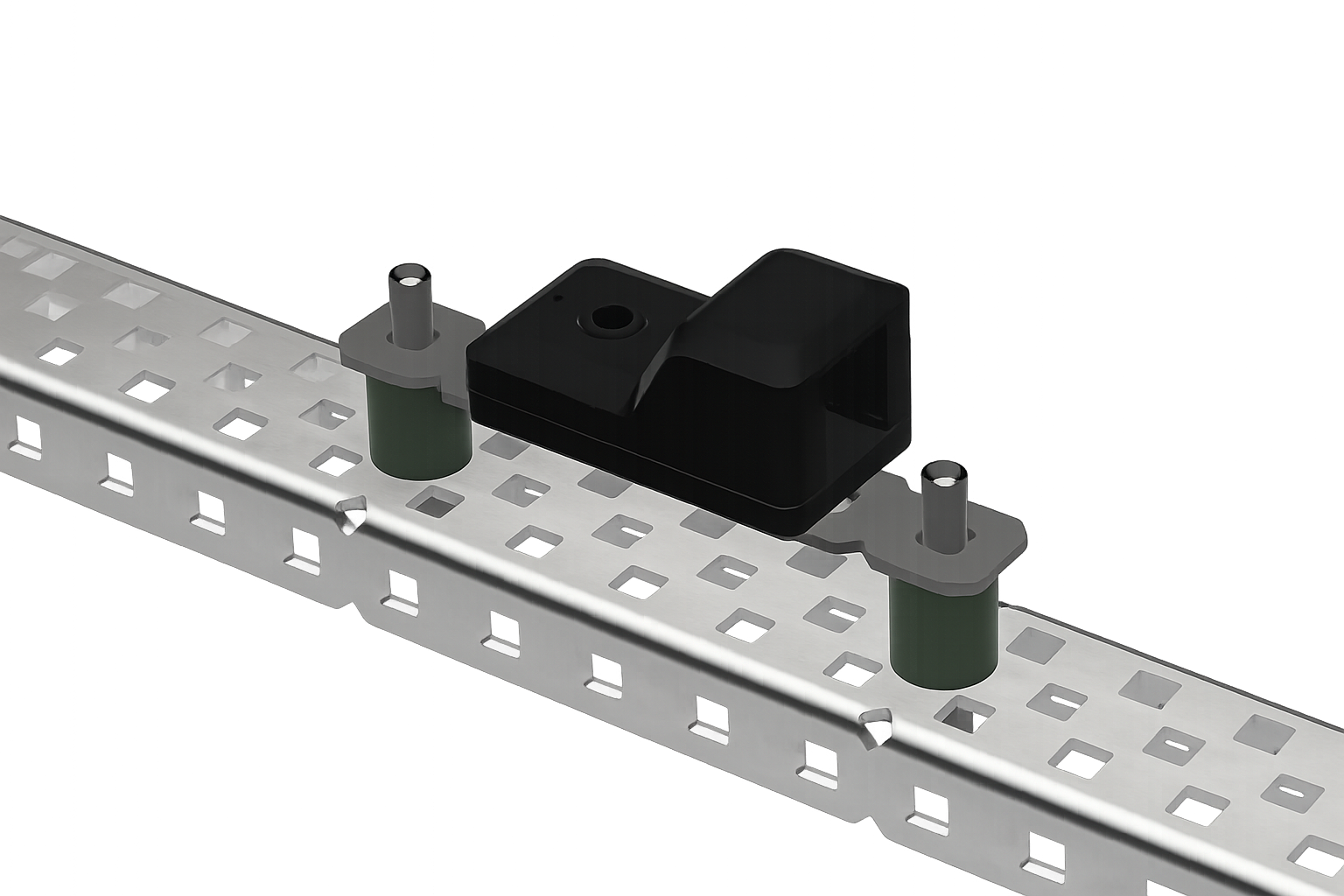
Place the port of your inertial sensor in the chassis.
PORT10, // Inertial sensor port
Inertial Scale
Sometimes what can happen is your inertial sensor will not read a full 360° after a full rotation. To fix this you can apply a scale factor to your heading. To find this value run the program, press Config then Odom Data. You should see Rotation: 0.00000 with the small decimal places flickering. Turn your robot clockwise in a full 360 until it ends up in the exact same spot it started. Use the value from Rotation: 360.15.
This is for extra precision, in most cases 360 will be fine to use for inertial scale
If the robot is not spun clockwise to find inertial scale, heading will be incorrect
360.15, // Inertial scale (reading after a full 360° turn)
Force Calibrate Inertial
When set to true it will recalibrate the inertial sensor automatically if after 1 second it drifts 0.05 degrees. This is to correct for when the robot is bumped during calibration leading the robot to think its spinning in circles. Set to false by default due to calibration taking longer than expected.
false, // Forces inertial sensor to recalibrate
Wheel Diameter
Plug in the wheel diameter of your drivetrain. You can use the diameters posted on the VEX website, or measure with calipers
2.75, // Drivetrain wheel diameter (in). Negative flips direction.
Run the program click on Odom Data on the Config Tab.
Take out a tape measure and move the robot 24 forward inches next to it.
If Y: position is not positive, use a negative wheel diameter. If it is not reading 24 double check your wheel diameter is accurate.
Drivetrain RPM
To find the RPM of your drivetrain, use the RPM of the cartridge inside your drive, and multiply that by the input gear teeth divided by output teeth. So for a drivetrain with blue cartridges with a 36 tooth input to a 48 tooth output is
450, // Drivetrain RPM. Cartridge * gear ratio, (Ex: 600 * (36/48) = 450).
Odometry
Tracking Wheels
This next section is for dedicated odometry trackers, which are non motorized wheels with encoders attached to them. For the best results with mikLib it is recommended to run both a forward and sideways tracker near the robots center of rotation.
If you are not using trackers leave them as PORT0
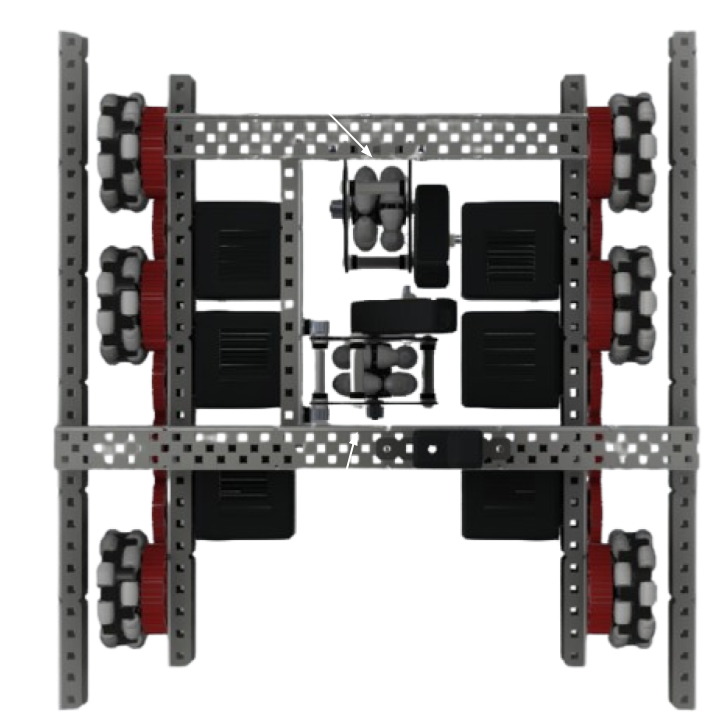
The forward tracking wheel is parallel to the wheels on the drivetrain, with sideways tracking wheel being perpendicular
Forward Tracker
The forward tracker measures the lateral distance of the robot.
Plug in the port for the forward tracker, you can use PORT0 if you are
not using one. You can also use PORT_A if you are using a three wire encoder.
PORT8, // Forward tracker port.
Run the program click on Odom Data on the Config Tab.
Take out a tape measure and move the robot 24 forward inches next to it.
If Y: position is not positive, use a negative wheel diameter. If it is not reading 24 double check your wheel diameter is accurate.
Plug in the wheel diameter for the tracker used. For 2" omni wheels use 2. Refer to the important tab above to make sure wheel diameter is correct.
2, // Forward tracker wheel diameter (in). Negative flips direction.
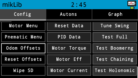
To find the center distance of forward trackers run the program,
press the Config tab, then hold down, and drag finger down to scroll downwards,
then press Odom Offsets. The robot should turn in place 10 times and display the offsets
on the brain.
You can also measure offsets manually. First find the center of gravity by balancing the robot on string, then use calipers or CAD to measure from that point to the center of the tracker. Refer to this chart to figure out sign. You know your offsets are correct if you turn your robot 180 degrees and the X and Y position stay relatively the same where it started.
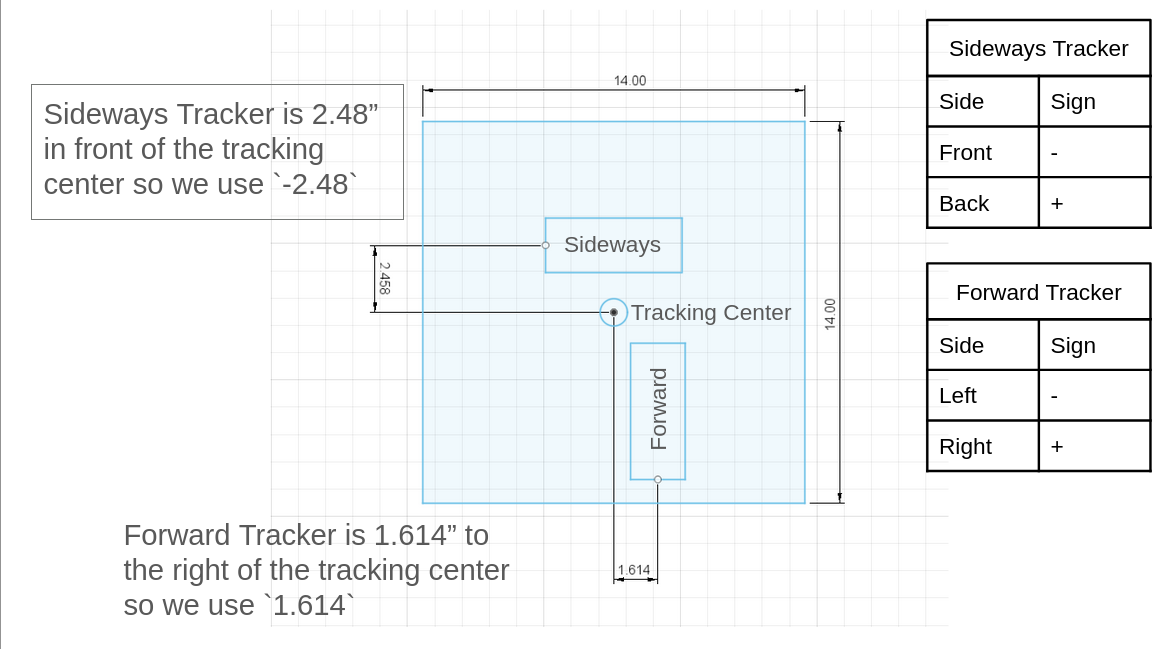
1.614, // Forward tracker center distance (in). Positive = right of center, negative = left.
Sideways Tracker
The sideways tracker measures the horizontal distance of the robot.
The sideways tracker is optional, however it is strongly recommended for drivetrain's using only omni wheels.
Plug in the port for the sideways tracker, you can use PORT0 if you are
not using one. You can also use PORT_A if you are using a three wire encoder.
PORT9, // Sideways tracker port. PORT0 if unused. Accepts "PORT_A"
Run the program click on Odom Data on the Config Tab.
Take out a tape measure and move the robot 24 to the right with the tape measure beside.
If X: position is not positive, use a negative wheel diameter. If it is not reading 24 double check your wheel diameter is accurate.
Plug in the wheel diameter for the tracker used. For 2" omni wheels use 2. Refer to the important tab above to make sure wheel diameter is correct.
-2.48, // Sideways tracker wheel diameter (in). Negative flips direction.
The same steps apply to the sideways tracker as forward tracker for finding center distance.
0, // Sideways tracker center distance (in). Positive = behind center, negative = in front.
Distance Resets
Distance resets are distance sensors placed on the faces of the robot and are used to reset the robots X or Y position. This is useful as error will start to accumulate using odometry wheels causing your actual position to drift. You can try it out in this simulator.
For best results 2 perpendicular distance sensors are recommended, as you can only reset one axis per wall.
To create a reset sensor, you need its port, position, and offsets.
mik::distance(PORT3, left_sensor, -4.873, -6.656)
To figure out its mounting position and offsets refer to this chart. It can either be a
front_sensor, left_sensor, right_sensor, or rear_sensor.
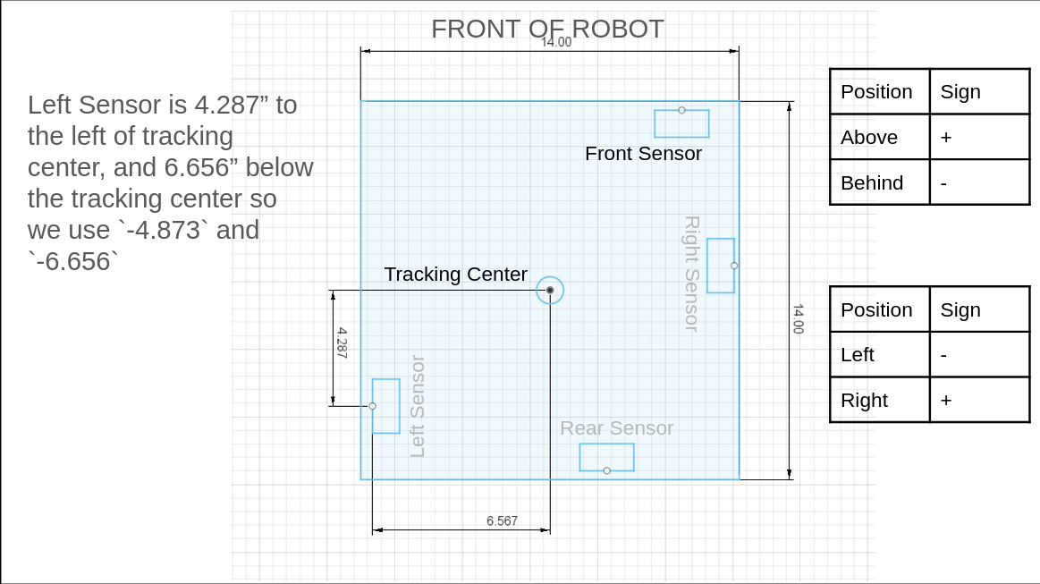
If you want to get the offsets automatically, place the robot in the center of the corner field tiles and ensure there are no obstructions.
Then on the Config Tab, scroll down, and press Reset Offsets.
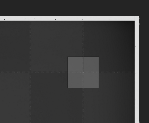
This method of automatically getting the reset offsets is not as accurate as measuring. Use it as a way of double checking measurements are correct.
Place all reset sensors inside the distance reset object.
mik::distance_reset({
    mik::distance(PORT11, left_sensor, -4.873, -6.656),
    mik::distance(PORT12, rear_sensor, -6, 4)
})
Completed Chassis Setup
Chassis chassis(
    // Left drivetrain motors (left/right is looking from behind the robot)
    mik::motor_group({
        mik::motor(PORT1, false, blue_6_1, "left front motor"),
        mik::motor(PORT2, false, blue_6_1, "left middle motor"),
        mik::motor(PORT3, false, blue_6_1, "left back motor"),
    }),
    // Right drivetrain motors
    mik::motor_group({
        mik::motor(PORT4, true, blue_6_1, "right front motor"),
        mik::motor(PORT5, true, blue_6_1, "right middle motor"),
        mik::motor(PORT6, true, blue_6_1, "right back motor"),
    }),

    PORT7,  // Inertial sensor port
    360,    // Inertial scale (rotation reading after a full 360° turn)
    false,  // Forces inertial sensor to recalibrate

    2.75,   // Drivetrain wheel diameter (in). Negative flips direction.
    450,    // Drivetrain RPM. Cartridge * gear ratio, (Ex: 600 * (36/48) = 450).

    PORT0,  // Forward tracker port. PORT0 if unused. Accepts "PORT_A"
    2,      // Forward tracker wheel diameter (in). Negative flips direction.
    0,      // Forward tracker center distance (in). Positive = right of center, negative = left.

    PORT0,  // Sideways tracker port. PORT0 if unused. Accepts "PORT_A"
    -2,     // Sideways tracker wheel diameter (in). Negative flips direction.
    0,      // Sideways tracker center distance (in). Positive = behind center, negative = in front.

    // Distance sensors mounted on a face of the robot
    mik::distance_reset({
        mik::distance(PORT8, rear_sensor, 4, 6),
        mik::distance(PORT3, left_sensor, -6, 4),
    })
);